
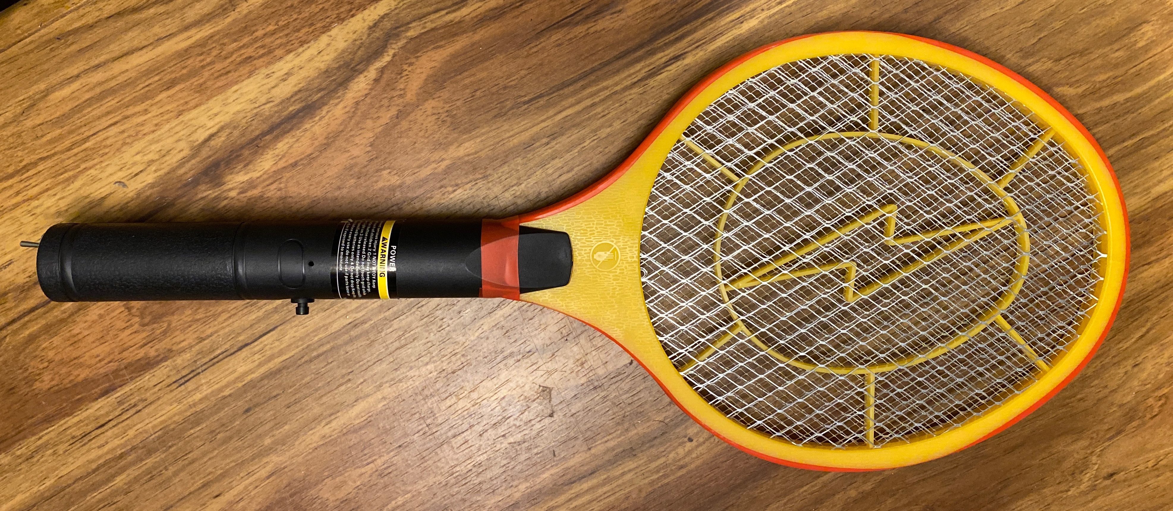
This is an electric flyswatter that has been modified to be more powerful. Your likely to find these in hardware stores, probably on end caps. It’s shaped like a small, plastic tennis racket with a trigger button, and a compartment for two AA batteries. To use it, you swat at flies or insects while holding the button, which shocks the bug as it’s being hit. They’re good to have when camping in areas with a lot of mosquitoes. You can purchase an Electric Fly Swatter by clicking the link below.
HOMEVAGE Electric Fly Swatter (2 AA Batteries Included) $14.99
Due to safety reasons, the shock is not that impressive. The only way a bug can be “zapped” is if it’s touching the inner and outer metal screen. Even then, it’s hard to know for sure if it’s being zapped because the voltage is very low. I wanted more power…
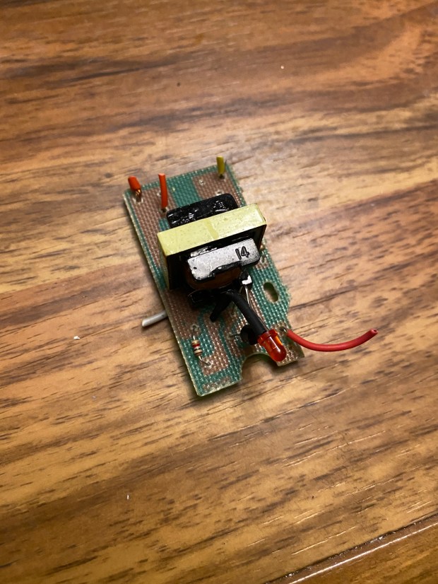
The electric fly swatter you see at the top is one that I modified a couple years ago. It has a much higher voltage output than the stock fly swatter, and I will show you everything you need to modify one for yourself. The modification consists of replacing the stock transformer inside with a Step Up Power Module, aka “Voltage Multiplier” to increase the voltage to as much as 700kV and create an arc (or spark) without anything touching the screens. The nice thing about these voltage multipliers is that they fit easily inside the handle of the fly swatter, and work off of two AA batteries.
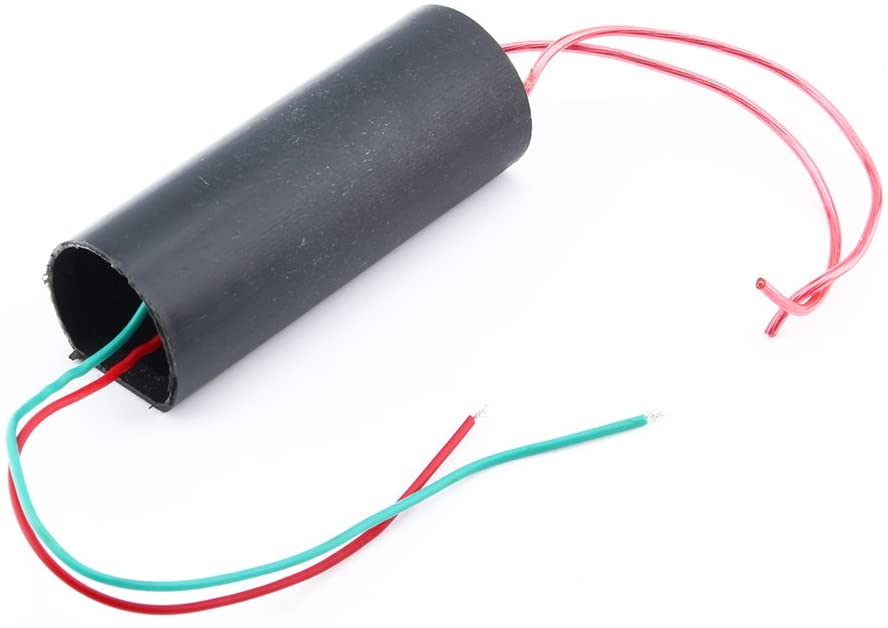
The Red and Green wires connect to the + and – sides of the batteries. The other two wires connect to the mesh screen .
You can purchase a one for yourself from Amazon $6.99 by visiting this link:
DC Boost Step Up Power Module High Voltage Generator DC 3V-6V,700KV
The reason I’m revisiting this project now is because I’ve been afraid to leave the batteries inside when its not in use. The button is easy to press, and doing so will cause a small arc. It’s possible for a child to grab it and shock themselves, or worse case, dropped onto the button and potentially cause a fire. So I revisited this project to add a safety switch onto the bottom.
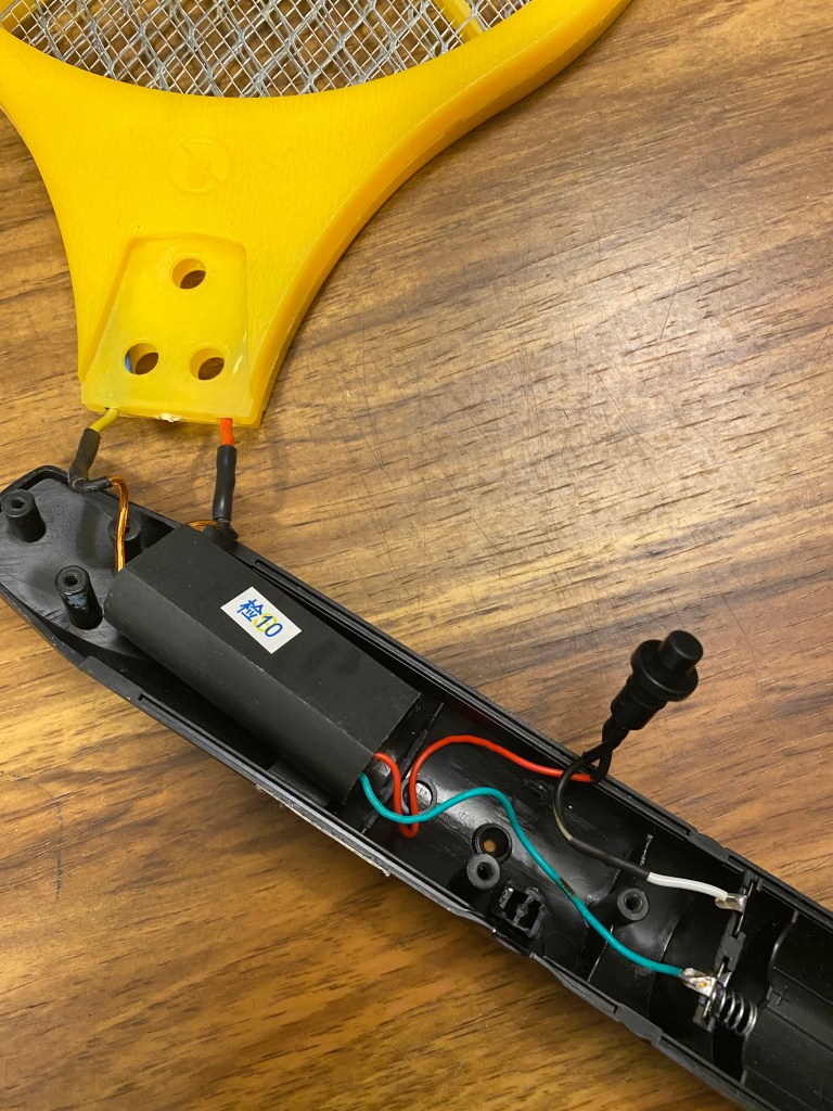
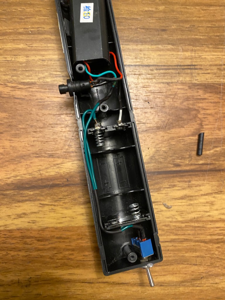
This is the inside of the flyswatter prior to installing the safety switch. The black trigger button was originally a programming switch for an aftermarket remote start system for a car. Most installers remove this button during the install to prevent the system from being reprogrammed by accident. It’s soldered in-line with the + wire coming from the batteries to the Voltage Multiplier. I replaced the stock button because it was broken during disassembly, but it would have worked as well and required less work.
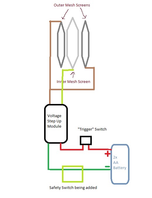
Here is a rough schematic I spent 5 minutes drawling in MS Paint. The bottom shows the safety switch that we are adding, which is going in-line with the negative wire from the batteries.
There are 3 wires coming from the mesh screen at the top, one wire for a center mesh (positive charge), and two wires for each of the outer mesh (negative charge). Both outer mesh wires will connect to a single wire from the module, and the other wire is connected to the inner mesh. It doesn’t matter which wire is which from the module, as long as the two outer mesh screens are connected to the same wire. This is honestly a simple circuit and great for beginners.
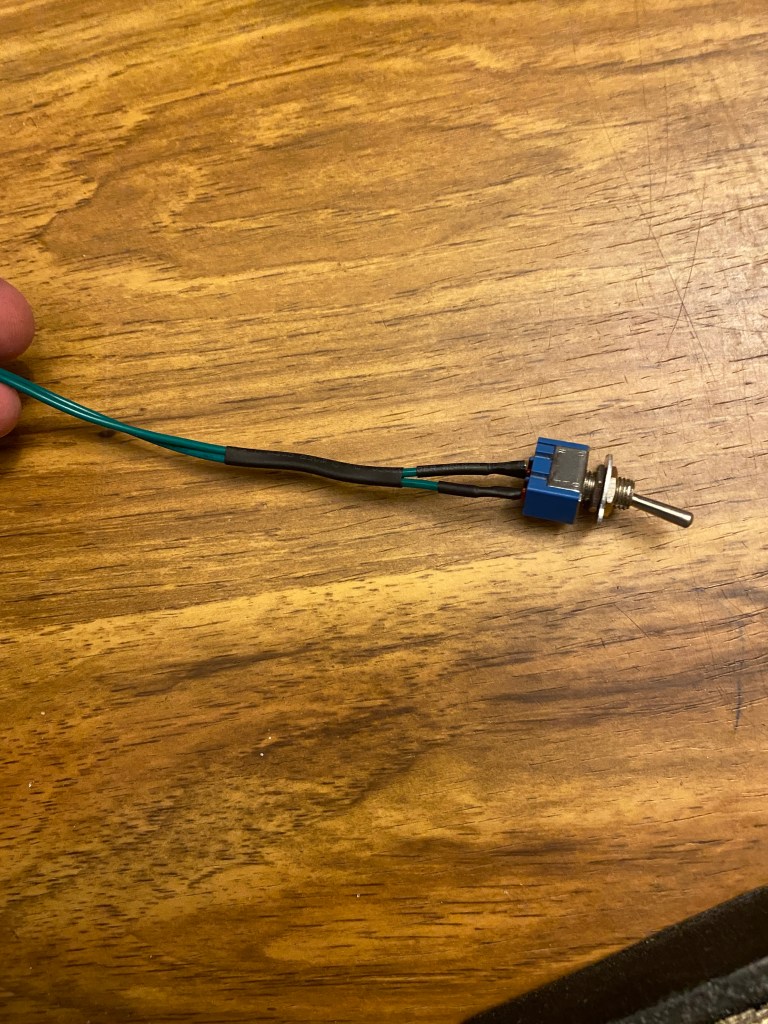
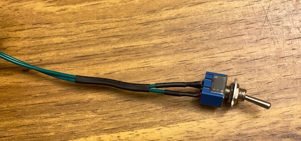
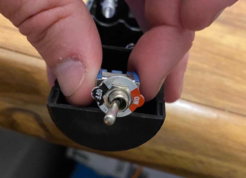
This is the switch I will add to be used as a safety switch. It has a small washer that reads “On Off” so that anyone can easily see whether the power is turned off or on. The current trigger switch will make the connection to the + side wire from the batteries, while the safety switch makes the connection to the – side. Both switches will have to be “ON” to allow the zapper to function.

There is limited room inside the handle, and since we’re working with high voltage we don’t want any wires to come loose or short out, so I’ll be soldering my connections and using heat shrink tubing.
This is my Hakko soldering iron. I’ve used many soldering irons over the years, and this is my favorite. The base is heavy enough to prevent itself from tipping over, and includes a wet sponge and wire mesh thing to quickly clean the tip. The iron itself heats up within 10 seconds, and shows a readout of the temperature. Hakko is a well known brand, so finding new tips is easy. You can purchase this Hakko Soldering Iron at this link:
Hakko FX888D-23BY Digital Soldering Station FX-888D FX-888 (blue & yellow)

This is standard 2:1 heat shrink tubing that I’m using for this application. You can purchase a similar assorted box of heat shrink tubing here:
650pcs Heat Shrink Tubing Black innhom Heat Shrink Tube Wire Shrink Wrap UL Approved Ratio 2:1 Electrical Cable Wire Kit Set Long Lasting Insulation Protection, Safe and Easy, Eco-Friendly Material
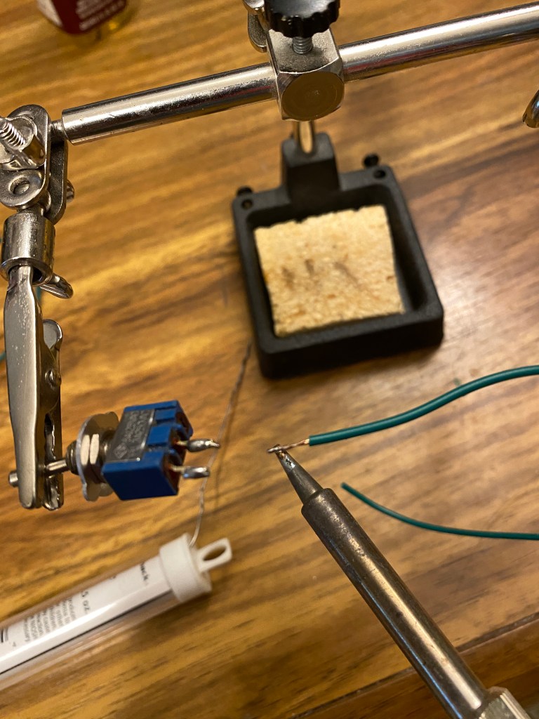
Always tin wires and contacts with solder before soldering them together. It’s makes soldering them together easier and creates a stronger weld. I also use flux when I have it nearby. Do not inhale the fumes from the solder, and use a fume filter if one is available.
.
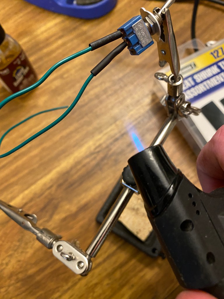
After soldering the wires to the switch, I slide some small pieces of heat shrink tubing over the wires and contacts. Normally I use a heat gun, or my solder reflow gun set at a low temperature, but I decided to use a torch because the tubing was so small. You have to be careful with a lighter or torch because it can quickly melt the material, which is why I’m leaving an inch between the end of the flame and the tube, and constantly moving the torch up and down. Always keep in mind that heat rises.

Heat shrink is better than electric tape at staying adhered to the wires. I normally do not use electric tape in cars or anything that requires movement and sudden temperature changes. Electric tape has a tendency to dry out and unravel over time, which would expose the wires that it’s supposed to protect.
I added a larger piece of heat shrink tubing around both wires to keep them together. I could have used tape for this, but since I already had the torch and heat shrink tube out, it was easier to use another tube. That section of wires will run along the side of the batteries, so keeping them snug will help prevent an accident when replacing batteries in the future.
I decided to mount the safety switch on bottom of the handle. Mounting it on the side would feel awkward with the toggle switch sticking up between your fingers, or poking the palm of your hand. There was no place higher that provided enough space inside, so the bottom was really my only choice.
I desoldered the original green wire from the negative battery terminal and replaced it with one wire from my switch. Then I soldered the other switch wire the the original green wire I just just desoldered.
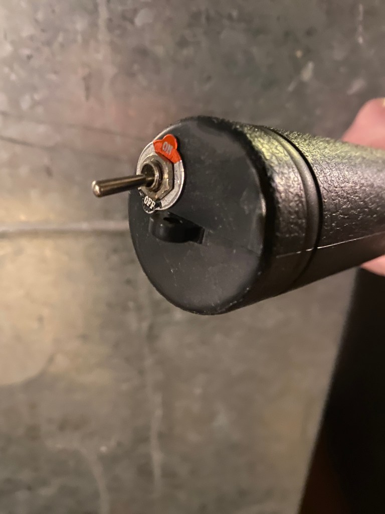
To mount this safety switch, I had to drill a hole into the bottom of the handle large enough for the threaded area part of the switch to fit through, but small enough to keep the nuts from falling through.
This is what the safety switch looks like after everything was reassembled.
Here’s a video of this electric flyswatter in use, so you can see the outcome and the arc created by the Voltage Generator Module thingy.
The arc will always occur where the inner and outer screens are closest. Unless a bug is on it, this flyswatter tends to always arc in that top area.
After I was finished, I tested to make sure all switches were working as expected. I hope you found this informative. Note that the links within this blog post are affiliated links, which means I get paid when they are used to purchase parts from Amazon.
